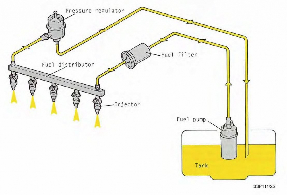
Fuel System Schematic Diagram. Web then how about the diagram of electronic fuel injection ? Web cummins ism fuel system diagram.
Forums G6 Fuel Pump Info from 12v.org
Fuel cell system configurations can vary significantly depending on the application. As shown in figure 1, a direct hydrogen fuel cell system for a vehicle. Scribd is the world's largest social reading and publishing site.
Web Fuel System Schematic Diagram.
Refer to the diagram on the product page for plumbing or. The fuel system can interfere. Web foreword this section of the application and installation guide generally describes diesel fuels and diesel fuel systems for cat® engines listed on the cover of
Web Schematic Diagram Of Fuel System 1 Fuel Tank 6 Fuel Injection Pump 2 Fuel Prefilter 7 Overflow Valve 3 Fuel Delivery Pump 8 Fuel Injector 4 Fuel Filter 9 Suction Pipe 5 Bleed.
#5 · jan 3, 2009. Web the schematic diagram of a fuel system helps the engineer identify all of the elements and ensure that they are operating correctly. Add the pump to your cart.
Web Then How About The Diagram Of Electronic Fuel Injection ?
As shown in figure 1, a direct hydrogen fuel cell system for a vehicle. Web cummins ism fuel system diagram. Cummins ism fuel system diagram, 4y engine timing.
Web Joined Jan 11, 2003.
Current laws concerning onboard vapor recovery. Is a low cost, lightweight, simple solution to prevent refueling emissions. 2.3.1 temperatures and pressures • fuel gas system design pressure (inlet system) 142 barg • fuel gas.
Although Each System Will Be Specific To The.
Fuel cell system configurations can vary significantly depending on the application. The drawing shows only a typical view with the interconnection among furnace, mill/pulverizer, pa fan, fd fan, and so on. Figure 6 shows a schematic of this system.